How to Measure a Steel Purlin
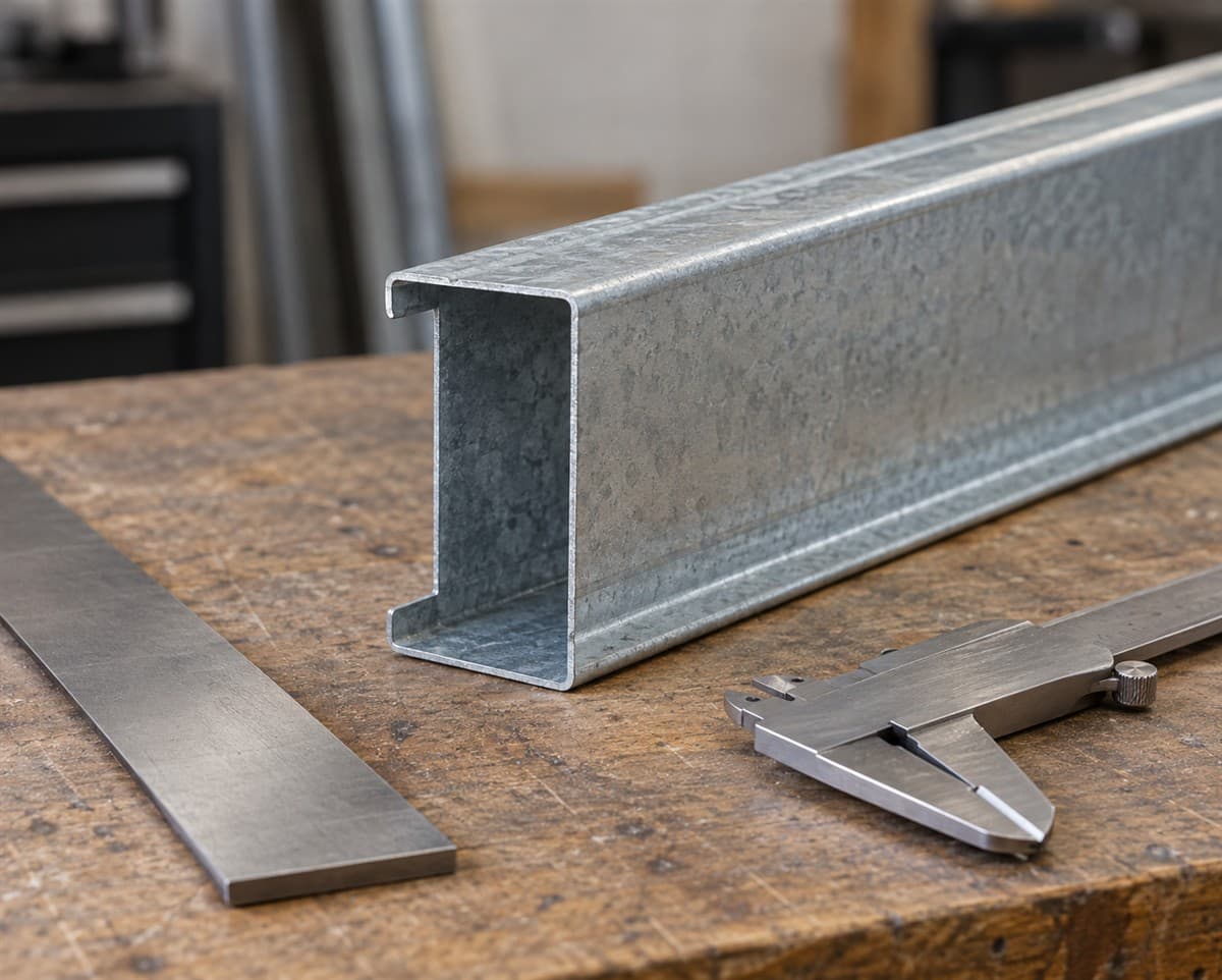
A purlin size name is a starting point. To describe an existing piece, record its end shape, depth, both flanges, return bends, length, and holes. Keep a sketch showing where you placed the measuring tool.
A purlin is a roof-supporting framing member. This method measures a loose spare or an already detached sample. It helps identify a part. It does not choose a size for a new roof.
Leave installed framing in place. If the only sample is overhead or damaged, ask a steel-building repairer to collect the missing measurements.
Set the sample up before reading the tape
Use a tape measure, a short ruler, a square, a pencil, paper, and gloves. A square is a tool with a right-angle corner. It helps show whether your tape crosses the section straight. A caliper has jaws that measure short distances or thickness.
Support the piece on a clear bench. Pick an intact end. Do not flatten a bend to make measuring easier. Photograph the sample before taking readings, including any damage.
Draw a simple outline of the end. The web is the middle face. The flanges project from its sides. A lip is the small return bend at a flange's outer edge. Label the two flanges separately so you do not swap their readings later.
Use C vs Z Purlins: How to Tell Them Apart if the shape is uncertain. Once the outline is clear, add measurement arrows to your paper sketch. Keep each arrow's start and end visible.
Measure the end shape one feature at a time
- Measure overall depth. Place the ruler across the section between its outermost top and bottom surfaces. Keep it straight across the end. Write “outside to outside” beside the result.
- Measure the first flange. Record the width using the outside faces as your reference. Show those faces on the sketch. Do not slide the tape diagonally around the bend.
- Measure the other flange. Give it a separate reading. Do not assume it is identical to the first.
- Measure each lip. Record the return bend's extent and sketch its direction. Keep this separate from flange width.
- Check the drawing's method. Compare your arrows with the dimension arrows on the section drawing. If they use different faces, record that difference before comparing numbers.
- Repeat at an intact area. Keep both readings if the section varies. Note whether dents or bent ends affected either one.
Your field measurements describe the piece you have. A catalog's nominal size is its named size. Do not assume that name uses the same reference surfaces as your measurement.
Treat thickness as a separate question
If you have a clean, accessible edge, a caliper can record the thickness you actually measure. Close its jaws gently against the sheet. Keep them off a curved bend. Note the tool and edge used.
Do not scrape away a finish to chase a reading. Label the result “measured thickness at this edge” rather than calling it the base steel thickness. Finish layers remain part of what the tool touches.
Copy any thickness or gauge label from the original paperwork. Gauge is a thickness designation. Keep it separate from your field reading. Ask for the candidate part's actual thickness information rather than converting a rough reading into a guessed gauge.
A thickness reading cannot identify steel grade. Steel grade describes material properties. If that information is needed for the replacement, obtain it from the original specification or have an engineer resolve it.
Add length and holes without changing the piece
Measure an intact loose member along its length, from end to end. Note whether an end is cut square, angled, or damaged. If you have only a short sample, record sample length. Do not label it as the full member's length.
For holes, choose one end as the reference end. Sketch the hole row. Measure from that end to each hole's center, then from a named edge to the center. A center is the midpoint across the hole.
Record the hole's visible shape. Round, slotted, torn, and unclear are different observations. A slot is an elongated hole. Do not file, drill, or enlarge a hole to improve the measurement.
These are descriptive readings of existing holes. The building's own drawings decide the required connection pattern, hole layout, overlaps, spans, and loads. If you cannot confirm them, stop the replacement choice and ask an engineer.
Copy this dimension worksheet onto your sketch
| Field | Reading to enter | How to label it |
|---|---|---|
| Shape | C, Z, or unclear | End photo filename |
| Depth | Your actual reading and units | Start and end faces |
| Flange A | Separate width | Which side of the sketch |
| Flange B | Separate width | Which side of the sketch |
| Lips | Separate reading for each | Direction and damage |
| Thickness | Reading or unknown | Tool, edge, finish left intact |
| Length | Full member or sample only | End conditions |
| Holes | Center locations and shapes | Reference end and edge |
| Drawing comparison | Same method or different | Page and dimension arrows |
| Material information | Exact original label or unknown | Paperwork location |
Write the units beside every reading. Do not rely on the reader remembering which ruler you used. Attach the end picture and hole picture to the same worksheet.
Compare a candidate without rounding away differences
Open 8-inch Cee purlin or 8-inch Zee purlin only after settling the shape. Ask for a complete section and hole drawing for the candidate. A general product name is not a match confirmation.
Compare each worksheet row. Keep differences visible, even when they seem small. Do not round a field reading to the nearest product name and declare the job finished.
For tracing the original piece through paperwork, use How to Find Purlins and Girts on Building Drawings. Your finished worksheet should make the measurement method clear enough to repeat. It should also leave material properties and replacement suitability unresolved wherever the evidence is missing.