What to Check When Purlin Holes Do Not Line Up
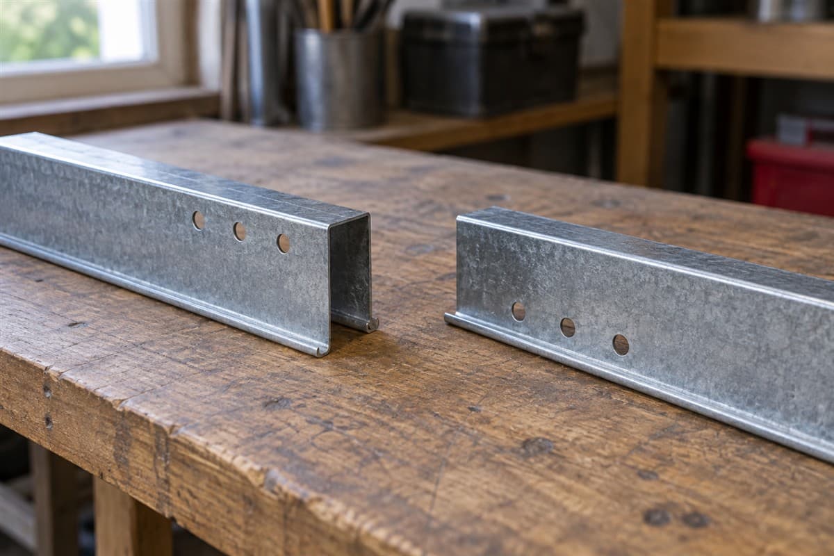
Put the drill aside. First compare the part marks, which ends you are matching, and the section directions. Holes that miss each other are a reason to investigate the pieces before changing either one.
A purlin supports roof panels. A girt supports wall panels. Both may have factory holes for their connections. A web is the broad middle face where those holes may appear.
This check is for loose parts on a stable surface or photographs of a connection. It does not require loosening installed framing. If the pieces are suspended or the connection is unstable, keep clear and call the installer.
Keep the mismatch as you found it
Take a wide photograph before moving any loose sample for comparison. Include each end and the neighboring parts. Then take a closer view showing the holes that do not match.
Write whether the problem occurred during a new assembly, a replacement, or inspection of an existing connection. Record the pieces' marks. If a code is unreadable, say so rather than borrowing the mark from a neighboring part.
Do not pull the pieces together with a bolt to see whether they will fit. Do not hammer an installed member or enlarge a hole. Preserve the visible difference so someone can compare it with the intended connection.
Gather a phone, tape measure, short ruler, pencil, and paper. You need a way to record locations, not a tool for modifying steel.
Run the identity checks in order
- Compare both marks with the parts list. Check every character. Note whether the list assigns both pieces to this particular location.
- Find the connection detail. A detail is an enlarged drawing of how parts meet. Check the sheet and location, not merely a similar-looking sketch.
- Name the reference ends. Call them end A and end B in your notebook. Photograph each end so the labels cannot get swapped later.
- Sketch the section directions. The flanges are the ledges extending from the web. Show which way they point and whether their widths differ.
- Record visible orientation marks. Some systems use stamped marks to identify an edge or direction. Copy what is present; do not assume every system uses the same mark.
- Compare the hole rows. Record the number, visible shapes, and locations on each loose piece. Keep each member's readings separate.
- Flag damage or changes. Note bent ends, stretched holes, extra drilled holes, or cut ends. Photograph them without trying to correct them.
Orientation can explain some mismatches in particular systems. It does not follow that flipping any installed piece is the right fix. Ask the installer to compare the actual members with this building's connection detail.
Measure from one named end and edge
On a loose sample, measure along the web from the named end to the center of each hole. The center is the midpoint across the hole. Then measure from your named edge to that center.
Draw your reference end and edge on the sketch. Use the same reference convention on both samples. Include the units with every reading.
If you measure one part from its left end and the other from its right, your notes will describe different references. The photographs should let another person catch that mistake.
Record a damaged hole as damaged. A slot is an elongated hole. Do not treat a torn round hole as a factory slot. If the original shape is unclear, leave the field uncertain.
These readings describe existing parts only. The building's own drawings decide required hole patterns, overlaps, bolt arrangements, spans, and loads. An engineer must resolve missing or changed structural connection requirements.
Use this before-modification checklist
Keep this checklist with the photographs. It helps turn “the holes miss” into an answerable question.
- The building location appears in a wide photograph.
- Both complete part marks are copied or marked unreadable.
- The parts-list entries show where each piece belongs.
- The connection detail's label and page are included.
- End A and end B are visible in the sample photographs.
- Each flange direction is drawn, including unequal widths.
- Hole readings use one named end and edge for each piece.
- Bent, torn, added, or hidden features are marked separately.
- The record says whether this is new work or an existing connection.
- The installer has the record before any physical adjustment.
Add one question beneath the list: “Are these the correct pieces and orientation for this location?” If the answer is yes, ask who will determine why the connection still differs.
Give the next person the difference, not a proposed fix
Send the installer the marked photographs, measurement sketch, and drawing pages together. State which holes fail to align. Include any discrepancy between the marks and parts list.
Ask for confirmation of member identity and intended orientation first. If the parts or holes are wrong, have the building maker or engineer define the correction. Do not suggest drilling, slotting, welding, or cutting as an assumed next step.
For identifying an unknown section, use C vs Z Purlins: How to Tell Them Apart. For a clearer dimension record, use How to Measure a Steel Purlin. Neither guide establishes an acceptable connection change.
Do not select a replacement from a general depth label just because its holes appear closer. The useful outcome here is a confirmed identity or a specific correction request. Once that question is answered, the installer can proceed using the building's actual connection requirements.