How to Choose Headwall Flashing for a Metal Roof
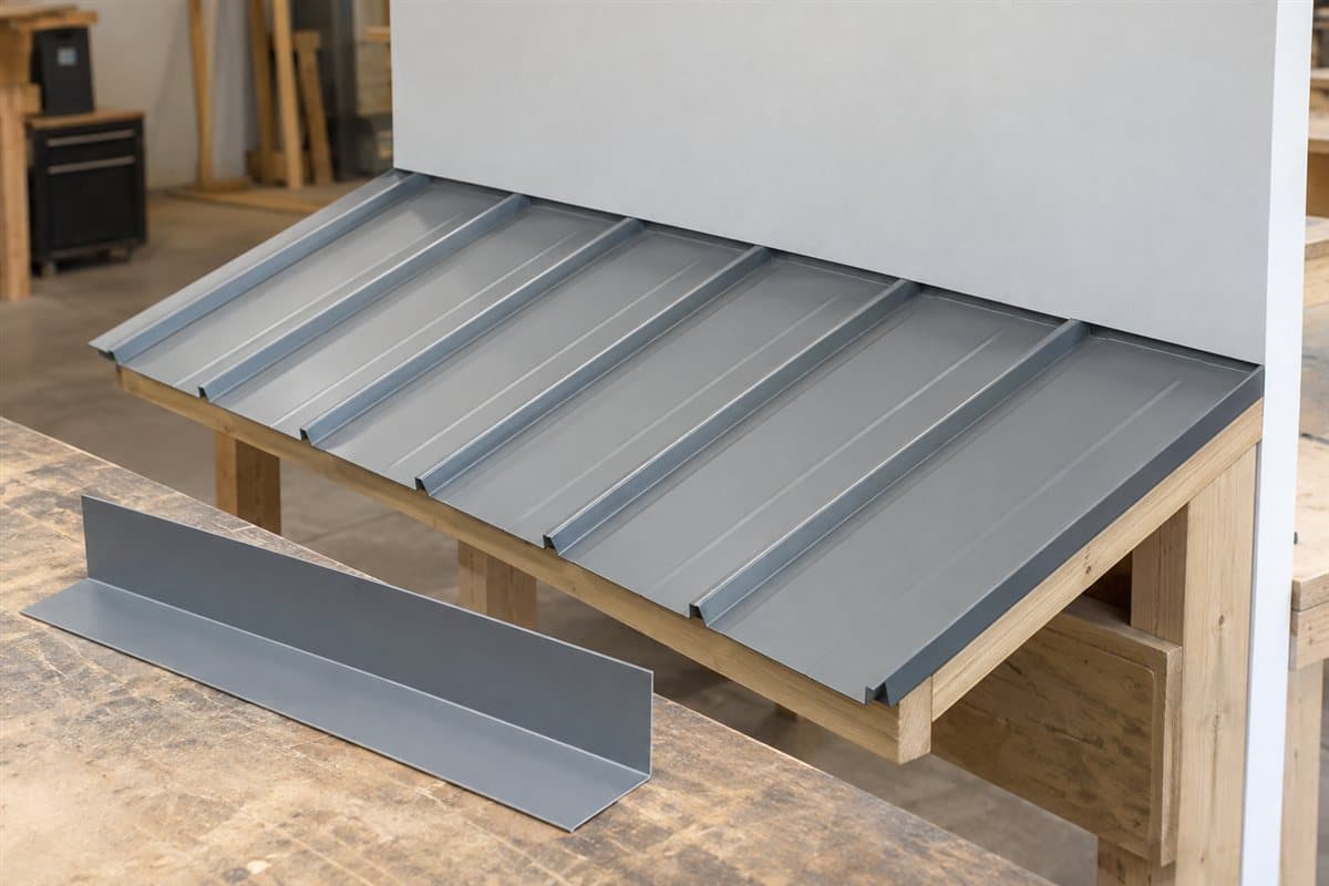
Headwall flashing belongs where the upper ends of roof panels meet a wall. Start by checking that location, then compare the roof-facing and wall-facing parts of the flashing. The part needs to fit both sides of the junction.
Some metal roof guides call this endwall flashing. Flashing is material shaped to direct water at a roof edge or junction. Cladding is the outer wall covering, such as metal siding. The flashing must work with the wall's water-draining layers as well as the roof.
This is a selection and junction-checking job. You can collect views, compare shapes, and identify missing pieces without opening the wall. Those checks help you choose the correct assembly before installation begins.
For roof work, use suitable fall protection and hire a roofer if you cannot inspect safely.
Separate a headwall from a sidewall
Look at the panel's ribs, the raised ridges in the sheet. At a headwall, the ribs run up the roof and end at the wall. A sidewall runs beside the roof slope instead. These locations use different flashing arrangements.
Photograph the junction from a safe position. Include the panel ends, wall covering, and both ends of the flashing run. Label the roof section and wall in your notes.
Do not confuse roof-to-wall flashing with head trim over a door or window. The location and water path are different. A similar bend does not establish that a door trim can finish a roof junction.
For an old barn with no drawings, look for the panel name on spare material, wrapping, or receipts. A profile is the panel's end shape. Use How to Match Old Metal Roof Panels when the profile name is unknown.
Follow the wall water path
Find what protects the flashing's upper edge. The wall cladding may cover it, or the assembly may use counterflashing, a separate piece protecting the upper edge of the lower flashing. Compare what is visible with the wall and roof instructions.
A water-control layer is the layer behind the outer wall covering that directs water outward. Its connection with the roof flashing matters. A strip fixed only to the exposed siding face may leave the hidden drainage path unresolved.
Keep hidden layers marked hidden. You cannot confirm the wall's drainage arrangement from an outside photograph alone. Ask a roofer to inspect that connection when the upper edge cannot be identified.
Do not pry off wall panels just to finish a shopping worksheet. Opening a wall creates a separate repair task. If the joint needs that work, plan it with the person doing the installation before choosing parts.
Build a shape record from loose material
Gather a ruler or tape measure, pencil, plain paper, gloves, and a phone camera. Use an intact loose flashing sample if one is available. A spare panel offcut can show the roof shape without disturbing installed sheets.
- Orient the sample. Identify the outdoor face, roof-facing leg, and wall-facing leg. A leg is a flat portion between bends. Photograph the end from that same viewpoint.
- Sketch each bend. Include small returns and hems. A return is a short section bent back toward the part. A hem is an edge folded back on itself. Do not leave out a bend because it looks decorative.
- Measure the flat portions. Write each reading beside its actual endpoints. Record the units. These measurements identify the existing shape; they do not prescribe flashing coverage.
- Describe the roof slope. Use existing pitch information or a safely measured record. Pitch means slope. Do not climb to measure it just for the parts comparison.
- Record the panel ribs. Compare the profile drawing with your sample. A closure is a shaped strip filling gaps at the panel ribs. If one is required, its shape must match that profile.
- Record the wall material. Note metal siding, wood covering, or masonry, meaning brick or block. Keep the upper-edge arrangement with that description.
- Compare a candidate drawing. Match its bends, angle, intended location, and connection arrangement. Leave any hidden layer or missing endpoint unresolved.
Your building's drawings or the panel maker's installation instructions decide flashing coverage, overlaps, fastening patterns, driving torque, and wind or snow requirements. Existing-part measurements are clues for matching, not new design dimensions.
Check the roof-to-wall drawing for completeness
Use this original checklist when reading a detail, meaning a drawing of how the pieces fit. It checks the whole junction instead of only the obvious bent strip.
| Drawing must show | Question to answer | If missing |
|---|---|---|
| Roof panel ends | Which profile meets the wall? | Identify the panel before comparing closures |
| Roof-facing flashing leg | How does it cover the panel ends? | Ask for the matching headwall section |
| Wall-facing flashing leg | What protects its upper edge? | Get the wall-layer connection detail |
| Hidden wall drainage | How does water behind cladding reach the flashing? | Have the hidden junction checked |
| Closure arrangement | Is a closure required, and which face fits? | Resolve type and location before counting |
| Seal locations | Which contact faces receive tape or sealant? | Get the specific product and placement instructions |
| Ends and corners | How does headwall meet sidewall or another edge? | Ask for both end treatments |
| Connection roles | Which fasteners join sheets and which reach support? | Keep those fastener selections separate |
Write a photo number or instruction page beside each completed row. If an illustration shows only the middle of a long run, look for separate end drawings. Both ends need an answer before parts are cut.
Understand the work that follows selection
Once the junction is understood, the installation plan should identify access to the wall layers first. Then it should set the order for sidewall pieces, panel ends, closures, and headwall flashing. The matching guide decides that order.
The installer fits and forms the loose flashing, prepares the contact surfaces, places required seals, and closes the joint. The wall's upper-edge protection is then completed as the wall detail shows. Finish by inspecting the ends and cleaning away metal chips.
Do not reduce that work to fastening a strip on the siding and covering its top edge with sealant. Likewise, do not pack every gap with foam. Closure and seal choices belong to the particular junction.
Keep the product list honest
The catalog has no separate headwall flashing entry. Its head or sill trim entry is not established as a roof-to-wall substitute. Keep the required flashing on your list as an unresolved sourcing item if its exact form is unavailable.
The listed Foam closure strips for PBR and R-panel and Butyl tape sealant may help only where the matching roof detail calls for those types. Both are pending confirmation. Neither product establishes the complete wall connection.
Use What trim pieces does a metal building wall need? to identify the wall trim around the junction. Use How to Use Butyl Tape on a Metal Roof for handling tape at a specified joint. Keep the completed drawing checklist with your shape record before selecting the rest of the parts.